|
SUSPENSION TEAM |
|
In order to meet the design requirements of a 2g turn double uneven A-arms with pushrod-actuated springs and dampers style suspension was chosen. Suspension points were designed using Racing by the Numbers software. These points cause the car to have low camber gains during roll of approximately .22 deg/deg in both the front and rear. There is a standard slightly negative camber of -0.5 degrees for cornering in the front. Afco 51 series shocks were chosen as the dampers, along with 165lb/in coil springs. A ride height of 4 in was designed with 1in of rebound and 1in of jounce travel. In order to achieve the designed suspension parameters, pushrods and bell-cranks were designed to achieve a motion ratio of approximately 0.91:1. This ratio provides the proper ratio of force transmitted from the wheel to the shocks/springs. The steering system was designed for a typical turning radius of 9ft at a steering wheel position of 90 degrees. The maximum expected steering wheel position is 90 degrees, but the team designed a tighter turning radius beyond 90 degrees to allow for potential driver errors. Parallel steering was chosen (as opposed to Ackerman) on the basis of the relatively high lateral accelerations experienced by the car due to tight maneuvering radii taken at speeds near tire slipping conditions. Most suspension and steering components were designed with an approximate factor of safety of 1.5. Braking on the vehicle is achieved through the use of Wilwood Dynalite Single calipers on all four wheels with dual Wilwood master cylinders. Brake disks are fabricated from Grade 40 gray cast iron with a 10 in diameter. A pressure bias is applied to the rear brake system via a Wilwood 2 psi residual pressure valve to achieve proper braking distribution. Force and temperature analysis were conducted on the disks, yielding a minimum factor of safety of approximately 1.4.
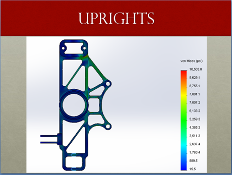
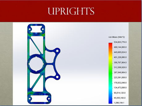
Our Progress 2.1 Technical ApproachOur first task was to learn how a suspension works and all the terms to go with a suspension, what those terms mean, and how changing those various aspects in turn changes the performance of the suspension. Following this research we proceeded to using a program called “Racing by The Numbers”. This program allows us to vary several parameters based off of our knowledge on suspension and then shows the resulting roll center height as well as other important dimensions. From here we can adjust our dimensions to change the most important parameters to ride to get the best suspension for the vehicle and competition. The program also allows us to look at the effects that roll and ride have on the characteristics of the car. Once we had finished with “Racing by the Numbers” and had definite points and placement of all the suspension components we were able to use MATlab, EES, and Excel to compute forces experience by the various components as well as the forces transferred to the frame through the tabs. With both the placement of the suspension components and the forces experienced we then moved on to the design stage. Most design work was completed in “Autodesk Inventor”. This was because it was due to its ease of use in design and FEA as well as its ease to learn and it being free to students. After each item was designed in Inventor and had FEA completed it was also exported to “SolidWorks 2013” where FEA was completed again as well as fatigue testing. It was found that “Inventor” always gave higher values for stress and was therefore used as another level of safety. The wheel centers, however, were analyzed using “PTC Pro/Engineer Wildfire 5.0” due to its advanced thermal and mechanical analysis which could be combined into a single analysis with detailed results. We then proceeded to start machining the suspension starting with the spindles since that is all we had the material for. We have since obtained the material for the majority of the suspension components, almost completed the machining of the spindles, fabricated the bushings, and began work on fabricating the uprights. While doing this we have been trying to obtain access and training to the waterjet so that we can continue work on the uprights as well as start the wheel centers and brake rotors. Along with this we have been designing the jigs for A-arms, obtaining material for suspension components, designing the steering including calculations for steering arm pin length, and working on budgetary and cost reports. Following the completion of the suspension we will proceed to fabricate the steering and braking components and assemble everything together on the vehicle. We have split up these tasks where certain members are focused on different aspects: designing, machining, obtaining material, FEA, gateways, and calculations, but we make sure multiple people are involved in each thing and everyone has multiple jobs. 2.2 BudgetThe budget is based off of the shared grant that the entire FSAE team received at the beginning of the year. This means that the 10,000 dollars needs to be distributed to some teams more than others. It was required this year that a new set of rain tires was purchased since last years were found o be too worn to use at the competition. The cost for the four tires and shipping was 779.16 dollars with a 20% discount given to FSAE teams through Hoosier Tire Company. Other components that have been purchased include the bearing cups used on the A-arms. Other materials that need to be purchased are aluminum for the fabrication of the uprights along with material that will be used to make a new rack along with the bell cranks. Fortunately some of the parts from last year’s car may be reused like the shocks along with the brake calipers. Through using these components again, the budget will be able to use to buy new parts that are needed or replace some parts that are starting to become worn from use on previous cars like the rack and pinion. Another factor that will help keep the budget down is the donation of an older FSAE vehicle that with parts attached that can be used on this year’s car. Along with this, donations have been made from many different companies allowing for the money to be spent elsewhere. The budget for the suspension team can be seen in Appendix B. 2.3 SchedulingThe schedule is based on client imposed deadlines as well as competition deadlines and our own goals. The client requests that by March 14th there is a rolling chassis with steering. This requires us to have the suspension and steering designed, validated, and attached by then. Our schedule therefore has us finishing the machining of the suspension and steering on March 7th one week before hand. Another client request is that by April 4th the car is self propelled. That means that the brakes must be completely, designed, validated, machined, and attached by then. Our goal is therefore to have that done one week before hand making the completion date for the brakes March 27th. The full suspension team Gantt chart can be found in Appendix C. 2.4 ProgressWe have all of the designing done for the steering, braking, and suspension systems and they have had finite element analysis completed on all components. This is ahead of schedule as the braking was not planned to be this advanced at this point in the semester. Fabrication has also been initiated and several components of the suspension system are completed. The work we will be doing for the remainder of the project consists of finishing the fabrication of suspension, braking, and steering system parts and assembling them. The fabrication is slightly behind schedule but we are looking to have everything completed on time if not ahead of time. 3. Accomplishments3.1 ResultsWe have created a four lug wheel center and spindle designs that will be capable of being used as a basis for future formula cars. We have designed and validated, through FEA, wheel centers, spindles, brake rotors, spacers, uprights, A-arms, steering rack and pinion, pushrods, bell cranks, tie rods, and steering arms. There are both inventor and SolidWorks files of these components with all of the forces, stress, and fatigue results included. Another result is the Excel and Matlab files used to calculate forces on the various components of the suspension as well as giving the specifications of the said components. |


