|
ENGINE TEAM |
|
Engine Team: Research on intake/exhaust design Learn Microsquirt tuning procedure Dynamometer test intake and exhaust Dynamometer tune finalized engine design
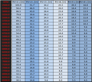
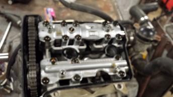
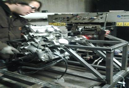
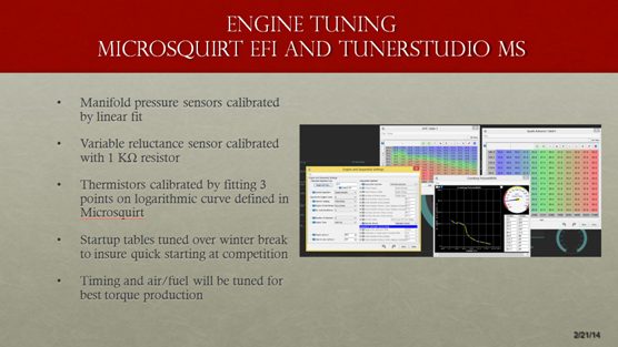
The major design considerations for the engine team involve the implementation of a 2007 Yamaha Genesis 80fi, 2-cylinder 499cc snowmobile engine. The primary design considerations on the power plant include a programmable Microsquirt fuel injection system (EFI controller), allowing for custom tune settings. The motor was benchmarked on an engine dynamometer (Flow Jet 901). Tuning software accompanied with the EFI controller allows for control of the fuel and ignition settings. Tuning these settings allowed for increased volumetric efficiency and power gains. Intake design features that are integrated onto the vehicle include an intake that also employs Helmholtz’s Resonance in its runner length. This uses pressure waves and their reflections to force more air into thecylinder. This technique is independent of RPM due to the pressure waves traveling at the speed of sound so the effect will only be seen at a design RPM. Below is a table of the calculated runner lengths as a function of RPM and Reflective Wave Value. The restrictor is also a feature that is designed at Bradley University. The final design selection incorporates a converging/diverging nozzle; the front orifice shaped of a 3/5ths ellipse and the diverging section is a conical nozzle tapering at 6 deg and having a pressure ratio of 97%. implementation of the engine dynamometer testing with the restricted intake, allow for the team to utilize the plateau effects in power that the motor produces. Through the proper fuel mapping and load settings on the dynamometer we are able to quantify are results and validate the maximum power range and speed.
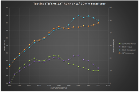
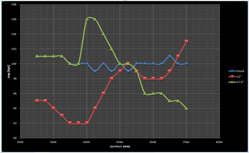
As you cam see above, we have been able to tune our intake design to bring our engines power output to within 5 ft-lbs. from stock. The graph on the left is a representation of our stock throttle body, versus our tuned test intake. The graph on the right is the validation of Helmholtz resonance boost in the Manifold Air Pressure. This shows the 17.5” effective runner lengths produce roughly 1 lb. of boost from the output RPM of 4500 until 5500. While the 12” effective length runners seem to produce the same boost starting at 7500 RPM.
The primary objectives of the engine and drive train team include having the donor snowmobile completely disassembled by Oct 26, which was completed, the objective is to have the previous FSAE car wired for new electronic fuel injection by Nov 8, aside from this another objective to be addressed starting during the same time is the intake and exhaust research. Fabrication of the first testable intake will be completed by January 21, this will allow for approximately 3 week window spanning February 10th to complete testing on the engine dynamometer to accommodate for any changes in design. Testing for the exhaust will also be completed throughout the month of January, immediately following the completion of the intake testing. The dynamometer data will be analyzed by Jan 20, and a final intake will be completed by Feb 10. Following the completion of the parts, the engine parameters will be adjusted to provide a high horsepower given the intake and exhaust designs, on the engine dynamometer by March 3. A new pedal assembly will be designed and fabricated by Feb 7. Following the assembly of the entire car all of the components will be wired together by April 4, allowing the fully assembled car to be tested on the chassis dynamometer no later than May 2nd. The engine will first be analyzed on the dynamometer in its stock form, to see the factory power curve for the engine. This will be used as a comparison to the finalized engine tune in March. Microsquirt electronic fuel injection will be installed and tuned on the engine to attempt to make more power from the factory intake and exhaust, and this tune will be used as a baseline once the test intake with the restrictor is put into place. Variables recorded during testing will include intake air temperature, barometric air pressure, engine speed, torque output, engine knock, exhaust gas temperature, and wideband O2 readings. The FSAE rules regulate the amount of airflow the engine can receive in an attempt to restrict the amount of power each team’s engine may produce. The regulation is as follows: “In order to limit the power capability from the engine, a single circular restrictor must be placed in the intake system between the throttle and the engine and all airflow must pass through the restrictor.” (2013 Formula SAE Rules). This along with the restrictor located in a place that is accessible for inspection, and the dimension of the diameter being equal to 20 [mm] with no moving parts dictate the design of the restrictor. When designing a restrictor the main goal is to acquire the maximum amount of airflow through the restrictor while minimizing the reduction in pressure drop.
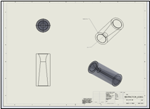
This picture depicts the geometry of the converging-diverging nozzle design. The ideal case would be designing a restrictor that fills the plenum (intake manifold) to a pressure ratio of approximately 97%. In the real world the effect of increasing the velocity has its limits, this limit occurs as the velocity of the air traveling through the restrictor reaches the speed of sound or Mach 1. This creates as semi-simplistic model of subsonic fluid flow into a highly complicated model of supersonic flow. The benefit of reaching this air speed is that the maximum mass flow rate occurs at Mach 1, while the downside is the creation of a shock wave which creates energy loss in the system.
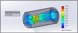
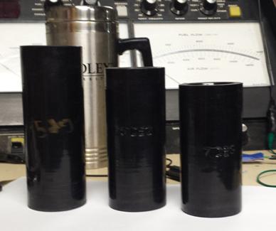
This figure depicts the 7 degree diverging nozzle extensive Mach number. Due to the complex behavior of compressible gases the Mach number represented here is only theoretical. For this reason the restrictor was designed as a converging-diverging nozzle. Due to the fact that diverging nozzles allow supersonic fluids to continue to accelerate. The design of the diverging exit nozzle is associated with the separation of airflow at supersonic flow. The diverging nozzle degrees that will be designed and tested are 7[deg], 6[deg], as well as 5[deg]. These angles will be researched by the Bradley Motorsports FSAE students to find the greatest slope that will show the smallest flow separation and turbulence. The restrictor is being 3-D printed using a 3-D printer. The specifications have been drawn using SolidWorks software, which can be manipulated into a .STL file. This .STL file will then be inputted into the 3-D printer, and variables; such as fill patterns and volume will be selected to produce a part with the correct rigidity as well as using less ABS plastic which creates a lighter weight for the restrictor. The 5 degree restrictor is shown below:
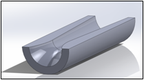
This picture represents the design of the 5 degree converging diverging nozzle design. Intake tuning will be done with the use of a custom manufactured intake with an adjustable volume and runner length. The plenum will be designed such that it can be separated into 2 separate volumes to test whether or not the engine should have a single or dual plenum. Since the firing order on the engine is only 180 degrees between cylinders there isn’t much time for the plenum to fill with air before the second cylinder fires. Exhaust gas temperature will be recorded to determine whether or not the cylinders are running at similar power levels with both plenum designs. The test intake is an essential part in our design process. Now that we have fixed the engine to the dynamometer, we can record torque outputs of the engine. This intake will begin as a very oversized intake, consisting of a plenum of 5 times the displaced volume of the engine. The will be reduced until the maximum amount of HP gain is seen. The test intake is created out of PVC piping in order to increase simplicity and manipulation, as well as reducing the manufacturing cost and time. The test intake also employs Helmholtz’s Resonance in its runner length. This uses pressure waves and their reflections to force more air into the cylinder. This technique is independent of RPM due to the pressure waves traveling at the speed of sound so the effect will only be seen at a design RPM. Below is a table of the calculated runner lengths as a function of RPM and Reflective Wave Value.
Exhaust tuning will be completed in a similar manner. A test exhaust will be built, which will eventually modified into the final exhaust to save on cost. The test exhaust will consist of separate pipes allowing different exhaust runner lengths to be tested as well as combinations of single or dual exhaust with resonators attached in order to quiet the engine at a mean piston speed of 914.4 m/min. The muffler will also be built to be adjustable, to allow different combinations of packing and silencers in order to minimize exhaust noise to below 110 dBA at the required engine speed. The final exhaust will be selected based on the best noise cancelling capabilities as well as the maximum horsepower produced by the changes in the exhaust. The final fuel injection adjustments on the engine will be applied to the engine after the final intake is built, and after the test exhaust has been welded into the final exhaust assembly. While on the engine dyno the air fuel ratio will be adjusted in each cell in the Microsquirt fuel injection to produce the highest power output for each cell given the restrictions of both the intake and the exhaust. The final timing will then be set and determined based on maximum power output, unless engine knock is encountered. In the case of engine knock the timing will be reduced 1-3 degrees from knock. After finalization of engine timing the fuel map will be calibrated again to ensure that no changes must be made to it after finalization of the ignition timing. |
|
OUR PROGRESS |
|
DESIGN |
